 Building Planes
Building Planes
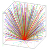
Building PlanesThe collection of Planes in a Layer define its geometrical properties, such as its physical extent and its adjacent Layers. Specifying Planes requires three kinds of information: (1) specification of the Plane Type, (2) specification of the adjacent layer (if appropriate) and (3) specification of the optical properties. It's also necessary to define the physical extent of the plane, which is done in the Edges dialog box.
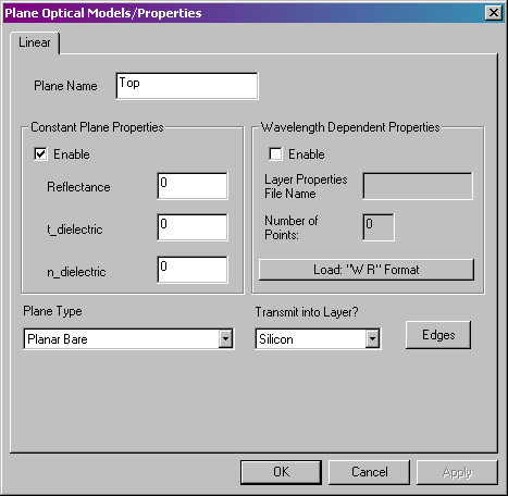
Plane Optical Models/Properties
dialog box.
Plane Name - Enter a short, descriptive name for this Plane. The name will appear in the list of Document View Area.
RaySim has a number of built-in plane types that model different optical interfaces. In addition, RaySim has a few auxilliary planes to aid in setting up more advanced simulations. The Plane Types are described briefly here.
| Plane Type | Purpose |
| Planar Bare | Simple optical interface. Reflection, transmission and refraction are controlled by the refractive indices of the two adjacent layers. Users must specify the adjacent layer into which transmitted rays will propagate. |
| Planar Single Layer AR | Simple optical interface with a single Layer Anti-reflection coating. Reflection, transmission and refraction are controlled by the refractive indices of the two adjacent layers as well as the refractive index and thickness of the dielectric coating (t_dielectric and n_dielectric). Users must specify the adjacent layer into which transmitted rays will propagate. |
| Planar Ideal | Idealised optical interface. Reflection and transmission are controlled by the critical escape angle - unity transmission for all incident angles less than the critical escape angle and zero for all other incident angles. Refraction is controlled by the refractive indices of the adjacent layers. Users must specify the adjacent layer into which transmitted rays will propagate. |
| Planar Reflector | Simple specular reflector. The reflectance is specified by a constant reflectance or by a wavelength-dependent reflectance. Rays are reflected specularly. Rays are not transmitted through this plane. |
| Lambertian Reflector | Simple diffuse reflector. The reflectance is specified by a constant reflectance or by a wavelength-dependent reflectance. Upon first incidence, a ray is split into a number of subrays, which are randomly reflected in a distribution equivalent to a Lambertian reflector. The number subrays is controlled by the Simulation Controls in the Batch Edit dialog box. Upon subsequent incidences, a ray is not split into subrays, but it is randomly reflected. |
| Translate Across Proportional | Auxilliary Plane. Rays incident upon this plane will be (1) perfectly reflected, then (2) translated onto another plane specified by the user. The ray is mapped a proportional distance from the apex of the first plane to the apex of the second plane. For example, a ray strikes the center of the first plane, it will be translated to the center of the second plane. this advanced feature requres careful selection of the order of Edge 1 and Edge 2 to get the desired mapping. |
| Translate Across Randomise Tail | Auxilliary Plane. Rays incident upon this plane will be (1) perfectly reflected, then (2) translated onto another plane specified by the user. The ray is mapped to a random location on the second plane. For example, a ray strikes the center of the first plane, it will be translated to a random point on the second plane. |
| Randomise Tail Reflect | Auxilliary Plane. Rays incident upon this plane will be (1) perflectly reflected, then (2) translated to a new, random location on the same plane. |
| Randomise Tail Transmit | Auxilliary Plane. Rays incident upon this plane will be translated to a new, random location on the same plane. Rays are not reflected and they remain in the same layer they are already in. |
| Randomise Tail Transmit Subdivide | Auxilliary Plane. Rays incident upon this plane will be (1) subdivided into a number of subrays as determined by the Simulation Controls and then (2) each subray will be translated to a random location on the same plane. Rays are not reflected and they remain in the same layer they are already in. |
Enable - Select this check box to enable plane optical properties that are constant with wavelength. Selecting this optical model will disable all other optical models.
Reflectance - This value is only used with the following planes: Planar Reflector and Lambertian Reflector. It specifies the wavelength-independent reflectance of the plane.
t_dielectric, n_dielectric - These values are only used with the following plane: Planar Single Layer AR. Enter the wavelength-independent thickness and refractive index (t_dielectric, n_dielectric, respectively) for the single layer anti-reflection coating.
Enable - Select this check box to enable layer optical properties that vary with wavelength, as specified by an external file that the user supplies.
Layer Properties File Name - Enter the name of the external file that contains the wavelength-dependent optical constants. The user must supply the data in a text file; each line must contain a list of two values separated by a tab character; the first value of each line is the wavelength, the second is the reflectance at that wavelength.
| wavelength1 | reflectance1 |
| wavelength2 | reflectance2 |
| wavelength3 | reflectance3 |
| wavelength4 | reflectance4 |
| etc. |
The pairs of data do not have to be ordered in increasing wavelength - RaySim6 will order the lists according to the wavelength value as they are read in from the Planes Properties data file.
There is no wavelength-dependent optical model for the single-layer anti-reflection coating (yet).