 Building Layers
Building Layers
Building LayersThe geometrical properties of a Layer, such as its physical extent and its adjacent Layers, are defined by its Planes and the properties of its Planes. Thus, Building a Layer requires only the specification of its optical model and properties, specifically the optical constants refractive index, absorption coefficient and scattering coefficient and their dependence on the wavelength of light (if any).
Editing the Layer Optical Model and Properties - All of the Layer parameters can be easily edited using the Layer Optical Models/Properties dialog box, shown below. Call up this dialog box by choosing Builders/Edit Layer from the Menu Bar or by double left clicking on the appropriate Layer listing in the Document View Area (Layers are listed in red text).
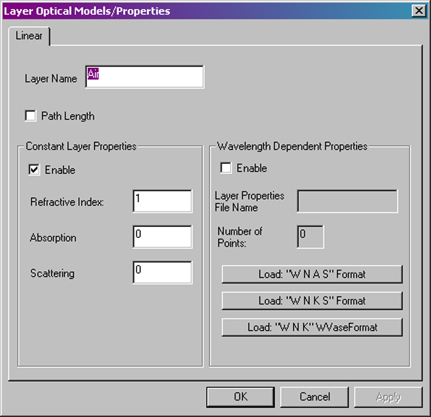
Layer Optical Models/Properties
dialog box.
Layer Name - Enter a short, descriptive name for your Layer. The name will appear in the list of Document View Area.
Path Length - Check this box to force RaySim to accumulate the effective optical pathlength of light travelling through this layer instead of accumulating the amount of light absorbed in this layer. The optical pathlength is is calculated by summing the intensity-weighted length of every ray that passes through the layer with the the absorption coefficient set to zero. The intensity-weighted length is the distance that a ray travels across the layer multiplied by its intensity.
Enable - Select this check box to enable layer optical properties that are constant with wavelength. Selecting this optical model will disable all other optical models.
Refractive Index, Absorption Coefficient, Scattering Coefficient - Enter the refractive index, absorption coefficient (in units of cm-1) and scattering coefficient (in units of cm-1) that best describe the optical properties of this Layer.
Enable - Select this check box to enable layer optical properties that vary with wavelength, as specified by an external file that the user supplies.
Layer Properties File Name - Enter the name of the external file that contains the wavelength-dependent optical constants. The user must supply the data in a text file; each line must contain a list of values separated by a tab character. RaySim supports three data formats: "WNAS", "WNKS" and "WNK", the latter of which is the standard output format for the WVase software package. The data format for each option is detailed in the table below. Wavelength (l) has the units of nanometers. Absorption (a) and scattering coefficients (s) have the units of cm-1. Refractive index (n) and absorption index (k) are unitless.
| Format | Col 1 Data |
Col 2 Data |
Col 3 Data |
Col 4 Data |
| WNAS | Free-space
Wavelength (nm) |
Refractive Index |
Absorption
Coefficient (cm-1) |
Scattering
Coefficient (cm-1) |
| WNKS | Free-space
Wavelength (nm) |
Refractive Index |
Absorption
Index |
Scattering
Coefficient (cm-1) |
| WNK (WVase Format) | Free-space
Wavelength (nm) |
Refractive Index |
Absorption
Index |
Where the complex refractive index of a material is given by

where n and k are the refractive index and absorption index, respectively, the absorption coefficient (a) is related to the absorption index (k) by
where l is the free-space wavelength expressed in units of cm-1.
The lines data do not have to be ordered in increasing wavelength - RaySim6 will order the lists according to the wavelength value as they are read in from the Layer Properties data file.
Note that, presently, only the real part of the complex refractive index (the "refractive index") is used to determine transmission, reflection and refraction at the interface between two materials.
Number of Points - The entry here shows the user how many data points have been loaded in from the Layer Properties file.
One important concept in RaySim is that while a ray is inside a particular Layer, IT ONLY INTERACTS WITH PLANES THAT BELONG TO THAT LAYER. All other Planes in other Layers in the Model are ignored. For this reason, every Layer must be bounded by enough Planes to make it "light-tight". Rays will leak out through gaps or backward Planes because RaySim will not be able to find a Plane for that ray to interact with. In this case, the ray is discarded into the "Lost" category. If you see non-zero entries in the "Lost" category of trace results is more than likely to be caused by a gap or backward Plane in the Model.
One of the consequences of the "light-tight" requirement is that every interface between two layers will necessarily have two back-to-back Planes, one for each Layer. This ensures that both layers are "light-tight".
The "Starter" document has a model called "Broken Box" that has a few problems related to "light-tighness". Try to fix these problems and get the total "Lost" ray intensity down to zero.