 Building Batches
 Building Batches
The controlling parameters of a trace simulation are stored in a RaySim6 Batch, specifically (1) the number and properties of the incident bundle of rays (ie, their wavelength, starting position and angle and intensity) and (2) the simulation control settings for the trace simulation. Determining the correct Simulation Controls is essential for fast and accurate trace simulations; and the best values depend on the simulation being carried out.
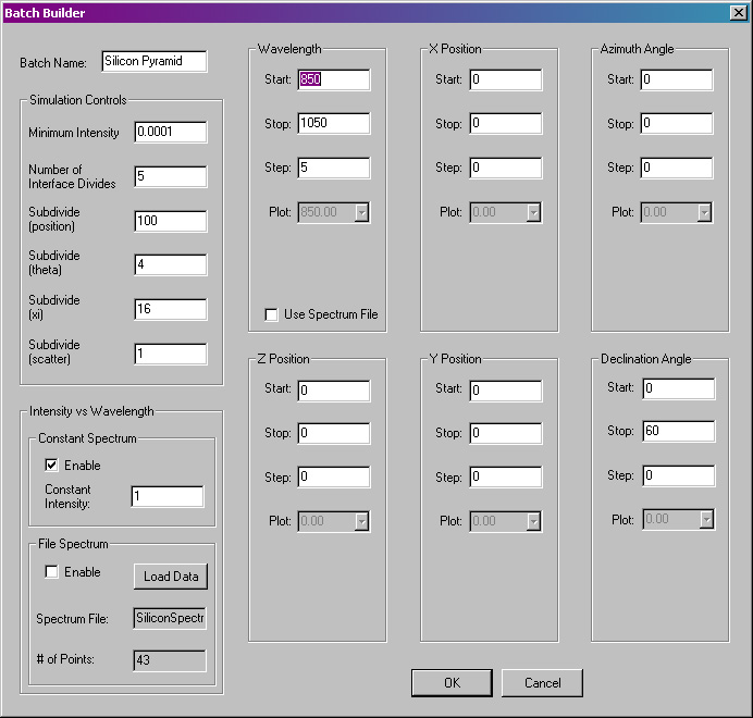
Editing the Batch Parameters - All of the Batch parameters can be easily edited using the Batch Builder dialog box, shown below. Call up this dialog box by choosing Builders/Edit Batch from the Menu Bar or by double left clicking on the apropriate Batch name in the Document View Area (Batches are listed in green text).

Batch Builder dialog
box.
Batch Name - Enter a short, descriptive name for your Batch. The name will appear in the list of Batches in the Document View Area.
Wavelength, Position, Angle - Here, the user can specify five of the properties of the incident bundle of rays: wavelength, x and y position (z position is under construction), azimuth and declination angle. The bundle of incident rays is constructed using the Start, Stop and Sep information entered by the user. The Start and Stop entries detail the first and final properties of the bundle of incident rays, and the Step entry details the distance between subsequent incident rays. For the example shown above, a bundle of rays will be generated with a spectrum of wavelengths, starting at 410 nm, with a 20-nm interval, and stopping at 1250 nm. Each of these 43 rays will be generated at x=0 and y=0 and azimuth angle= 0 and declination angle=0.
When the Step entry is set to zero, only one ray will be generated for that property, and that property will be set to the value of the Start entry.
The trace simulator will create a bundle of rays that is a matrix representing all possible combinations of wavelength, position and angle prescribed by the Batch Builder settings. Thus, the total number of incident rays is given by R=W*X*Y*A*D, where W is the number of wavelength steps, X is the number of steps in the x direction and so forth. For the above example, if the Start X and Start Y entries were changed to -10 and the Stop X and Stop Y entries were changed to +10 and the Step X and Step Y values were changed to 1.0, the total number of incident rays would be 43*21*21*1*1=18,963.
Note: care must be taken when setting up the bundle if incident rays to avoid excessively large numbers of rays. The trace simulation time increases superlinearly with the number of incident rays. Not only does it take proportionally longer to trace more rays, but the overhead associated with temporarily storing large numbers of rays increases as well.
Constant Spectrum, File Spectrum - Here, the user can specify the intensity of the each incident ray in one of two ways. Constant Spectrum gives all incident rays the initial intensity specified by the entry value. File Spectrum gives all incident rays an initial intensity that depends on wavelength (only) and is specified in the external file that is entered in the edit box called "Spectrum File". The user must supply the data for the spectrum in a text file; each line must contain one pair of values separated by a tab character; the first value of each line is the wavelength and the second is the intensity of light at that wavelength. An example representing the intensity (expressed as mA/cm2/micron) as a function of wavelength is shown below. Wavelength varies from 410 to 1250 and the intensity values are separated from the wavelength values by a tab character.
|
wavelength1
|
intensity1
|
|
wavelength2
|
intensity2
|
|
wavelength3
|
intensity3
|
|
wavelength4
|
intensity4
|
|
etc.
|
etc.
|
The pairs of data do not have to be ordered - RaySim6 will order the pairs according to the wavelength value as they are read in from the File Spectrum data file.
When an incident ray is created, RaySim6 will look up the wavelength in the table of data and set the intial intensity to the value specified in the second column, interpolating if necessary. If the incident ray has a wavelength that is less than the smallest entry, the intensity of the smallest wavelength value will be used. If the incident ray has a wavelength that is greater than the largest entry, the intensity of the largest wavelength will be used. Note well that if the user intends that the intensity data represents spectral density (eg., mA/cm2/micron), then it's generally necessary to choose a Start, Stop and Step Wavelength values that correspond to the entries in the File Spectrum data file.
See the section called How RaySim6 Traces Rays for more information about how the simulation controls influence the trace simulation time and accuracy.
Minimum Intensity - RaySim6 will cease to trace subrays when their intensity falls below a certain value that is given in part by the value specified in this edit box. Each ray in the bundle of incident rays can be divided into, at most, N=2ID*P*TH*XI*S subrays, where ID, P, TH, XI and S represent, respectively, the entries in the Number of Interface Divides, Subdivide (Position), Subdivide (Theta), Subdivide (Xi) and Subdivide (Scatter) edit boxes. When the intensity of an individual subray falls below MI/N, where MI is the entry in the Minimum Intensity edit box, it is discarded and its intensity is added to the Remainder intensity.
Choose a value for MI that is roughly equivalent to the product of the required precision and the incident intensity. For example, if the intensity of an incident ray is 1.0 and a precision of 0.1% is required, then a value of MI=0.001 is suitable. Smaller values of MI will increase the trace simulation time and vice versa.
Number of Interface Divides - RaySim6 will split rays into two subrays each time it encounters a partially transmitting interface between two layers. The number of times an incident rays is allowed to be split in this way is limited by this entry. Once this limit is reached, subrays are not subdivided further, but are either transmitted or reflected in Monte-Carlo fashion using a stochastic model instead.
The number of trace rays can grow very large due to Interface Divides. An incident ray can generate as many as 2ID+1 - 1 subrays by the Interface Divide process.
Subdivide (Position) - RaySim6 has a special type of Plane, called Randomise Tail Subdivide Transmit, that allows rays to be subdivided into some number of subrays, as specified by this entry. Rays incident on this type of Plane will be subdivided into P subrays, where P entry in this edit box, then, each ray will be transmitted into its adjacent Layer (as specified by the properties of that Plane, NB if you specify the same Layer that the Plane belongs to, it will be transmitted, but remain in the same Layer), and its tail will be shifted to a new, random position on the Plane. Note that once a ray has been subdivided by this process, it is not subdivided further by this process, but is transmitted into its adjacent Layer with a new, random position instead.
Subdivide (Theta) and Subdivide (Xi) - RaySim6 uses these entries to generate the stochastic equivalent of a uniform angular distribution of light in the model. RaySim6 actually divides the sphere (or hemisphere for reflecting Planes) into TH*XI equal solid angles and then generates one subray inside each solid angle (with direction determined stochastically). Note that once a ray has been divided by this process, it is not subdivided further by this process, but instead is redirected in a new, random direction in Monte-Carlo fashion using a stochastic equivalent of a uniform angular distribution of light.
Subdivde (Theta) and Subdivide (Xi) will generate as many as TH*XI subrays.
Subdivide (Scatter) - RaySim6 uses this entry to generate the stochastic equivalent light travelling through a turbid medium. RaySim6 divides a ray into S subrays, then allows each ray to travel a randomly determined distance through the medium, where that random distance is determined using the stochastic equivalent of a turbid medium. Note that once a ray has been divided by this process, it is not subdivided further by this process, but instead is propagated for a random distance, determined using a stochastic equivalent of a turbid medium. In either case, it is then scattered using the rules described in the previous section Subdivide (Theta) and Subdivide (Xi).