 About RaySim6
  About RaySim6
 RaySim6 is a graphical user interface (GUI) software program for geometrial ray tracing. RaySim6 is written by Jeff Cotter, originally to support his PhD work on the light trapping in silicon solar cells (starting in 1996), and more recently to support modeling and simulation research at the University of New South Wales' Centre of Excellence in Silicon Photovoltaic and Photonic Devices. The RaySim program is written in C++ with Microsoft Windows MFC support, using the MS Visual IDE. The first version of RaySim had little GUI support - all the model parameters and optical constants were hard coded. Over the years, the program has been adapted to make it easier for non-programmers to use and to include more optical features that are interesting or important to silicon solar cell researchers. RaySim6 is the first public release of the software, released in mid 2004, after a major reorganisation of its data representation.
The program has been developed primarily for the simulation of silicon solar cells, although it has been used for the development of glass static concentrators by Dr. Nicholas Shaw, as well as a few other confidential projects here and there. RaySim6 has many features, most good, some bad. The best-of-all feature is that IT'S FREE! although there are a few restrictions on its use and distribution. Other features include:
- Geometrical ray tracing - thus it's best for models that have features that are large compared to the wavelength, coherence length, spatial extent of the light source. This excludes many important optical phenomena, such as diffraction and interference.
- Linear, time-invariant materials - RaySim6's trace algorithm requires linear superposition and time-invariance (so it can trace individual rays independently of the rest of the system). This excludes many interesting materials and phenomena, for example, multi-photon interactions like energy upconversion, although the author is working on this during 2005.
- Fast, Threaded trace algorithms - RaySim6 uses fast and accurate algorithms of storing and tracing rays. On the author's 1.1 GHz Pentium III laptop, RaySim6 can make almost 8 million trace operations per minute. It's fully threaded, such that the user can carry on with other work without noticible degredation of computer response. The number of in-trace rays is limited by the physical memory of the system, and while the simulator will use hard disk storage space as swapped memory when the number of rays grows large, the simulator performance slows greatly in this case.
- Fully multi-chromatic - RaySim6 can simultaneously trace a spectrum of rays, a group of spatially distributed of rays or a group of angularly distributed rays or all combinations of the above, provided the model describes linear, time-invariant materials.
- Document/Batch/Model/Layer/Plane architecture - simulations are organised in Documents consisting of one or more Batches that specify a set of trace parameters. Each Batch contains a single optical Model that is comprised of one or more Layers of similar or different optical materials. Each Layer is bound by four or more Planes of similar or different optical properties. Copy/Paste at the Batch, Layer and Plane levels allows multiple similations to be setup in little time.
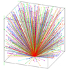
- Visual GUI model building - models are displayed in stick-figure representation and can be moved and rotated for a pseudo 3D visualisation. Partial traces can be displayed on the model and moved and rotated for a pseudo 3D visualisation. Optical models are specified using GUI dialog boxes, including material properties, interface properties and geometrial extents. Batches and Models can be added, edited or deleted using point and click mouse operations or with window menus and toobar buttons.
- A variety of optical models - for Layers and Planes. Layer optical models include constant and dispersive properties, absorption (Beer's Law), scattering (Lambert's Law), refraction (Snell's/Fresnel's Law) and (coming soon) Stokes' Energy Downshifting. Plane optical models include constant and dispersive reflectance, bare interfaces, idealised interfaces (unity transmission, except where total internal reflection applies), single-layer antireflection coatings, Lambertian surfaces, and a variety of idealised surfaces necessary for constructing optical unit cells.
- Optical pathlength calculation - Calculate the effective optical pathlength in any Layer by applying the limit of zero absorption.
 About The Author
Coming soon. Contact him at Jeff Cotter.