 Building Edges
Building Edges
Building EdgesEvery Plane is defined by two vectors, called Edges. In it's entirety, the physical extent of a RaySim model is defined by an organised collection of Edges - two Edges per Plane, many Planes per Layer, many Layers per Model.
Each Edge uses six values to specify its position and direction within the physical Model. They are {x, y, z} and {X, Y, Z}. {x, y, z} represents the location of the tail in 3 dimensional cartesian coordinates, and {X, Y, Z} represents the length of the Edge vector in the corresponding directions.
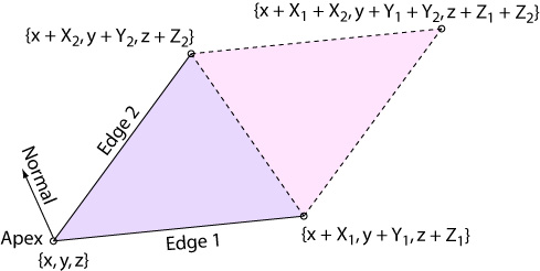
Edge geometry. Two edges
define a triangular shaped plane (magenta) or parallelepiped shaped plane (pink)
RaySim fixes the tail {x, y, z} coordinate of both Edges at the same point, forming the apex of the Plane. If a triangular shaped Plane is specified, the Plane is bounded by the two Edges and a third vector that joins the two heads of the Edge vectors, as indicated by the magenta triangle in the figure above. If a parallelepiped shaped Plane is specified, the Plane is then bounded by the two Edges and two additional vectors that are translated as shown in the figure above. In parallelepiped is indicated by the magenta and pink areas in the figure above.
Planes are One-sided. One very important concept of RaySim Planes is the Normal vector. RaySim will automatically calculate (and normalise) the vector cross product of the two Edges, forming a third vector, called the Normal vector. In RaySim, the Normal vector ALWAYS POINTS TOWARD THE BACK FACE OF THE PLANE. This is important because rays traced by RaySim DO NOT INTERACT with the back face of Planes - they pass right through the back face without reflecting, transmitting or refracting.
(Why does the Normal vector point to the back face and not the front face in RaySim? Well, for the same reason that electrons are negatively charged, I guess.)
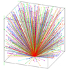
Therefore, Planes are one-sided. Rays will only interact with the front face of a Plane. The Normal vector points toward the back face of a Plane. Therefore, in the construction of a simple box (see figure below), the Normal vectors of all six Planes must point outward in order for light inside the box to interact with the Planes. In cases where a Normal vector points in the wrong direction, RaySim may not trace according to your expectations. In many cases, rays will become lost and will be discarded by the simulator. RaySim will render the Normal vectors on the Model View so you can be sure they point in the correct direction.
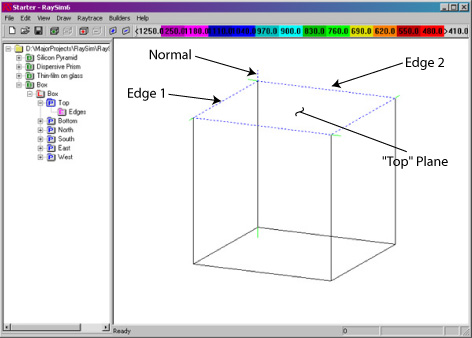
RaySim will draw the Normal vector, although it can be hard to see at distant
zoom settings. The Normal of the highlighted plane (Top) is drawn with a dashed
blue pen. The other normals are drawn with a green pen. Think porcupine -
all of the normals that enclose this "light-tight" box point outward.
RaySim has a button on the Define Plane Edges dialog that allows you to swap Edge 1 for Edge 2 called "Edge1 <--> Edge2". Clicking this button will swap the two edges and flip the direction of the Normal vector by 180 degrees. Think of it as the spatula button.
In advanced simulations, you can use the one-sidedness of Planes to build some fancy models.
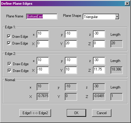
Editing the Edges and their Properties - The two Edges of a Plane can be easily edited using the Define Plane Edges dialog box, shown below. Call up this dialog box by choosing Builders/Edit Edges from the Menu Bar or by double left clicking on the appropriate Edge listing in the Document View Area (Edges are listed with a magenta symbol). The Define Plane Edges dialog can also be accessed from the Plane Properties dialog box by clicking the Edges button.
Plane Optical Models/Properties
dialog box.
Plane Name - Enter a short, descriptive name for the Plane. The name will appear in the list of Batches in the Document View Area.
Plane Shape - Select either Triangular or Parallelepiped.
x, y, z - Enter the {x, y, z} coordinate of the apex of the Plane. Both Edges will have the same tail location, at the apex of the Plane.
X, Y, Z - Enter the length of the Edge in the {X, Y, Z} direction. The Edges must point in different directions.
Draw Edge - Select this feature to toggle the rendering of any Edge for the Plane between on (checked), dashed (greyed), off (unchecked). The Draw Edge feature is a good way to switch off drawing of parts of your Model in order to improve presentation of the Model.
The Normal vector is calculated automatically each time you change any of the Edges.